Circuit Snippets: Managing Reset Across Multiple Boards
4 May 2019
This is the first post in a series I’d like to do of little Circuit Snippets: Small little circuits that you can hopefully cut and paste and use in your own designs, as appropriate. Or, take inspiration and modify them and do something new and interesting. (If you do something new or interesting, I’d love to hear about it via social media or email!)
So today’s Circuit Snippet is all about managing reset in systems with multiple boards. I’m a big fan of building complex systems out of LOTS of simpler systems. I gave a talk at the 2018 Hackaday Superconference about it, even. It’s really useful for a few reasons to include a shared Reset line as a sideband-channel in complex system. Let’s look at why this might be useful:
So, let’s say you’ve got a system that looks a little like this:

Example System with One Controller and Several Nodes
A controller talks to several nodes and tells them what to do, and when to do it. In the systems I design, the nodes are usually simple embedded systems using an 8- or 32-bit microcontroller (I really like CAN bus, so I really like the AT90CAN and SAMC21 series from Atmel/Mirochip), and the controller is a much more complicated system running embedded Linux, or something similar.
If you design your firmware and hardware right, this works really well! The nodes pop online as soon as power comes up, and wait for commands from the controller. A little while later, the controller finishes booting, and begins sending commands. You can implement a software reset command over the communication bus, and reset and even jump to the bootloader and update firmware with no problems.
But what if you’ve got a software bug? Or even worse, a hardware bug? What if something damages a board while it’s out of reach, and your software resets no longer work?
We can increase the robustness of this system immensely just by adding a single share side-channel reset line:
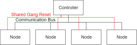
Example System from above with a shared Gang Reset
Here’s what we want to happen: When the system is powered on, the nodes are held in reset until that reset is released by the controller. This keeps all the nodes in their “hardware safe” modes until the controller is able to start doing the controlling. If a node is misbehaving, the controller can hard-reset it. If we accidentally flash some bad firmware, or if our firmware has a bug that causes it to get lost in the weeds, we have a hard reset that will let us get back to our bootloader.
Additionally, we want to be able to test the individual nodes separated from the controller. On the benchtop, for example, hooked up to a separate power supply. We also want to be able to use our in-circuit debugger and programmer. So any circuitry we attach to the reset line should default to “running” when the system isn’t attached to the controller, and should allow the programmer/debugger to pull the reset line appropriately.
A few possible approaches to this:
- Hook an output on the controller to all the reset lines on all the nodes. The nodes will have
appropriate pull-up resistors so they default in the not-reset state when disconnected. The
controller will have a big pull-down so everything starts in the reset state when connected.
- Even with fairly weak pull-ups, when you add a lot of nodes, this requires the controller to have an extremely strong pull down, and to be able to drive the reset line strongly. This also doesn’t accommodate boards that have different reset levels (3.3v vs 5v, for example), and when a programmer is connected to the full system, it will yank around the reset lines of everything. This could be the solution for a small system, though.
- Put a buffer on each of the nodes, pull up the input of the buffer, and have the controller drive
that.
- This is a way better solution! If you get the right buffer, it fixes the issue with voltage conversion. Depending on your pull-ups, you might still need more drive strength than your controller, has, though. And the programmer might not be able to overcome with drive strength of whatever buffer you’ve chosen.
- Buffer the nodes, buffer the controller, and have the node buffer drive a MOSFET attached to a
pull-up.
- Now we’re talking! The node buffer provides the benefits of (2). The controller buffer provides enough drive strength for all the pulling resistors, and driving a MOSFET means that the pull strength on the node boards is only what is provided by the pull resistor, so the programmer doesn’t have to overcome the buffer.
How have I achieved this? Here’s the circuit on the controller:
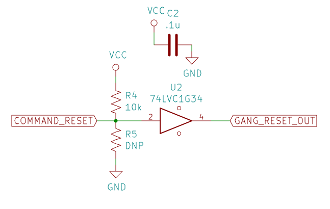
Controller-side gang reset circuit
The COMMAND_RESET signal is controlled by a microcontroller on the controller. It pulls the reset
signal low when we want our nodes to come out of reset. R4 pulls the input of the buffer high. (R5
is included but not populated for completeness sake. Want to change the behavior of the circuit?
Swap R4 for R5.) GANG_RESET_OUT is the output signal distributed to all the controllers.
The 74LVC1G34 buffer chip is a deliberate choice: It has a relatively high output drive, up to 32ma on the TI version of the part (at 5V VCC). It also has equal drive strength at both high and low logic states (this is important, we’ll see in a second).
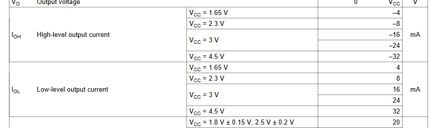
Drive strength from [TI Datasheet](http://www.ti.com/lit/ds/symlink/sn74lvc1g34.pdf)
So, a little math: 5V / 32 mA = 156 ohms. So we can drive up to 156 ohms of combined pull-down strength.
Now, on the node side, here’s the circuit we’re going to use:
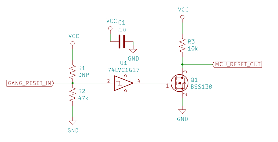
Node-side gang reset circuit
Important bits: GANG_RESET_IN comes from the controller. R2 pulls down the input of the buffer.
This determines the state of the buffer when it isn’t connected to the controller, and you can
either pull it high or low. Because of the drive strength of the buffer on the controller,
as long as you’re using a fairly weak pull-up or pull-down, pick whatever pull-value the node needs.
In this case, this node needs to be pulled down (which makes the output low, which means Q1 isn’t
conducting, which means MCU_RESET_OUT is high).
R2 is fairly weak at 47k. How many 47k pull-downs can this buffer drive? Well, parallel resistance is: R_out = (1/ (1/R1 + 1/R2 …)). For us, R_out = (1/ (x*(1/47k))), and R_out = 156 ohms (from above). That give us 301. We can have 301 nodes at 47k (not accounting for wire resistance, or anything else). So, lots more nodes than we’ll ever want for this system.
The specific buffer chip doesn’t particularly matter in this instance, and if you select a 5V tolerant part (like the 74LVC1G17), you can use this circuit to control either 3.3V or 5V reset logic chips. Similarly, Q1 isn’t important, as long as it’s a logic-level FET. I really like the BSS138 as a general purpose logic-level NFET. R3 should be whatever pullup you need for your programmer and microcontroller. And that’s that! Your programmer can pull around that weak R3 with no problem, as long as the controller isn’t holding the node in reset. When the node is disconnected from the controller, it will pop up normally, and you can do your debugging, no problem.
Hopefully this design helps you out a little bit! Questions? Comments? Notice I’ve made a mistake or haven’t addressed something? Drop me a line (check the column to the left).